Network Creation
Establishing a valid network is crucial for the simulation to run properly. There are three key components involved in creating a valid network: Road Design, Terminals, and fixing Network Errors. Each component is discussed in more detail below.
Road Design
1. Drawing Roads
When creating a new Network in the software, the network will initially be empty, with no road layouts displayed. Roads must be created to enable vehicle travel between Terminal locations. If there is no access to Terminals, the simulation may be unable to run.
To create a road, the Draw tool can be used. The video below demonstrates the process of creating a road network going down the main pit ramp. The steps covered include:
1️⃣ Verify that the snapping mode is set to Geometry.
2️⃣ Activate the Draw tool (✏️) and choose the desired Lane Type to be applied.
3️⃣ Specify points to create the center line of the road. These points will automatically generate edges connecting them.
4️⃣ Inspect the drawn network to ensure there are no issues or misalignments.
🖱️ Use the middle mouse button to smoothly pan the viewport while drawing the network, and use the mouse wheel to zoom in and out for a better view of the area.
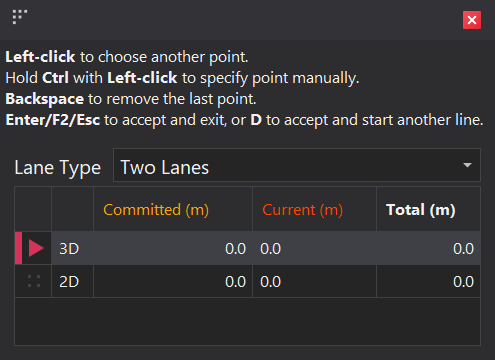
When the Draw tool is active, the information panel in the bottom right corner displays shortcuts and distance information about the road being drawn. The 2D distance measures the horizontal length on a flat plane, while the 3D distance includes both horizontal and elevation changes, providing the true path length on the terrain
Commited: This is the length of the edges that have already been drawn.
Current: This represents the distance of the uncommitted edge, from the last committed point to the next point (where the mouse cursor is positioned)
Total: This is the combined distance of the Committed and Current edges, giving the total length of the path from the first point to the current cursor position.
2. Editing Roads
Once roads have been drawn, adjustments may be necessary. These can include adding additional points, moving existing ones, or registering points to a surface— all of which can be done using the Point Edit tools.
The video below demonstrates how to add points to an existing edge and move them into the correct positions. The steps covered include:
1️⃣ Activate the 'Add Point to Edge' tool
2️⃣ Add points to relevant edges
3️⃣ Exit the 'Add Point to Edge' tool
4️⃣ Activate the 'Move Points' tool
5️⃣ Move relevant points to reposition the road
6️⃣ Exit the 'Move Points' tool
3. Intersections
Intersections are automatically generated when three or more edges meet. The following video demonstrates the automatic creation of two 'T' intersections.
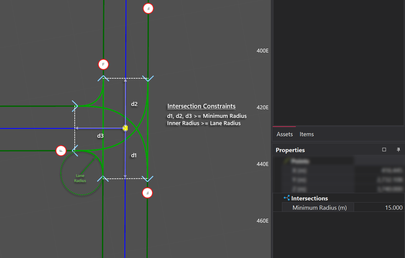
Intersections are constrained by both the Minimum Intersection Radius and the Turning Radius of lanes within the intersection. The image below shows these contraints and how they affect the intersection geometry.
4. Speed Signs
Speed signs are assigned to lanes and apply across the full length of their associated arc. Positioned at intersections at both the start and end of the arc, the default speed limit—set in the Lanes step—is automatically applied as the road is created. Chaning the default speed limit, can be achieved in two ways.
The video below demonstrates the two different methods for updating speed signs on lanes. The steps covered include:
Speed Sign Tool
1️⃣ Activate the 'Speed Sign' tool from the toolba.
2️⃣ Select Speed Sign to apply
3️⃣ Place Speed Sign at intersections located at both the start and end of the arc
Properties Panel
1️⃣ Select the arc to be updated
2️⃣ Assign speed signs to lanes in the Properties panel
🖱️ Double-clicking an edge highlights the arc it belongs to, which can help identify the network sections impacted by any property updates.
5. Manual Intersections
Since arcs can span long distances between intersections, different speed limits or lane types may need to be set for specific sections of the road. This can be achieved by manually adding intersections to divide large arcs into smaller segments, allowing speed signs and lane types to be assigned to lanes between these new intersections
The video below demonstrates how to use manual intersections to divide a large arc into smaller segments and assign a new speed limit. The same process and logic apply when assigning a new lane type. The steps covered include:
1️⃣ Check the length of the current span of road
2️⃣ Activate the 'Add Intersections' tool
3️⃣ Insert intersections at appropriate points along the road
4️⃣ Double-click an edge to activate the newly created arc.
5️⃣ Use the Properties Panel to set speed limits for the lanes
Terminals
1. Adding & Moving Terminals
When creating a new network in the software, the only Terminals that will be present will be the Sources and Destinations. Fixed Infrastructe Terminals such as crushers and go-lines need to be manually added to the network.
To add and position these fixed items, the Terminal Edit tools can be used. The video below demonstrates the process of manually adding a crusher terminal and covers the following steps:
- Use the Add Terminal Location tool to add the 'CR1' crusher and select the Prefab type.
- Set the Terminal's initial position by snapping it to the topography and adjust its bearing using the mouse.
- Use the Move Terminal Location tool to fine-tune the placement of the terminal.
- Use the Rotate Terminal Location to adjust the terminal’s orientation and bearing.
- Set the Width property of the Terminal to 0 meters to simulate the truck’s approach and departure path to and from the crusher.
⌨️ Press the ESC key to exit the current tool and switch back to Select mode.
2. Joining Terminals
Terminals need to be joined to the network in order for vehicles to reach them. There are two main methods to achieve this: using the drawing tool or the auto connection tool, both of which are explained below.
✏️ Draw Tool
When using the draw tool, an edge can be drawn directly to a single terminals Connection Point or its Access Point. Connecting to the Connection Point will maintain the terminal's bearing, while connecting to the Access Point will align the terminals' bearing with the connecting edge. Both of these techniques are shown in the videos below.
Access Point
Connecting directly to a terminal's access point aligns its bearing with the connecting edge. This alignment is preserved even if the terminal is moved. The video below demonstrates how to use this connection method.
Connection Point
Joining to the Connection Point preserves the terminal's bearing, but as a result, the roads may curve, potentially causing errors. To avoid this, the terminal must be rotated to the correct direction before making the connection. The video below demonstrates how to use this method effectively.
🪄 Auto Connection Tool
The Auto Connection tool streamlines the process of linking terminals to the network, enabling bulk connections with minimal effort. To use the tool, simply select the terminals to be connected, activate the tool, and click the point on the network where they should join. The tool will automatically create edges from the selected network point to the access point, aligning the terminals' bearings appropriately. The video below demonstrates how to use this tool.
Fixing Network Errors
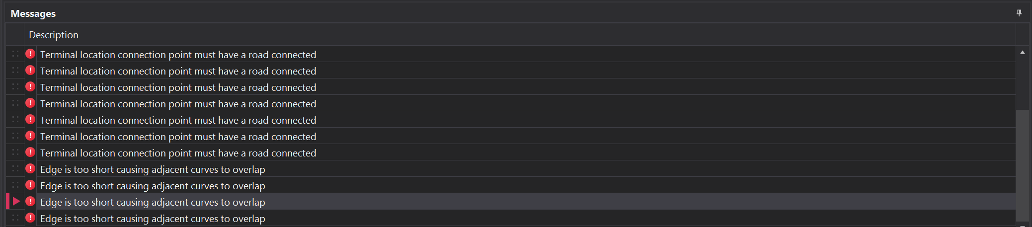
When designing the network, there is undoubtedly going to be some errors that arise. Problematic items will appear in the designer either with a red indicator arrow above them, or incased in a red box. Errors will appear down the bottom in the Messages panel. Double-clicking on a error will reposition the camera to focus on the error.
The main type of errors are categorised below along with how to fix them.
| Error | Description |
|---|---|
| Terminal location connection point must have a road connected | This error occurs when a terminal in the network is not connected to the main network. To resolve this, ensure the affected terminal is properly connected to the network using the Terminal connection tools. 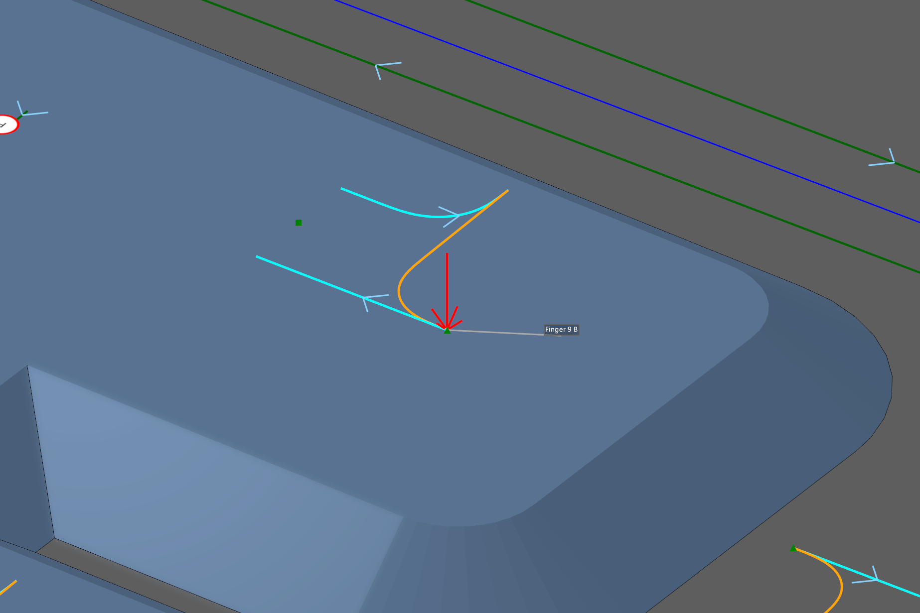 |
| A corner has an angle exceeding the maximum: | This error occurs when the curvature of a road is too sharp. To resolve this, adjust the corner to reduce the angle. 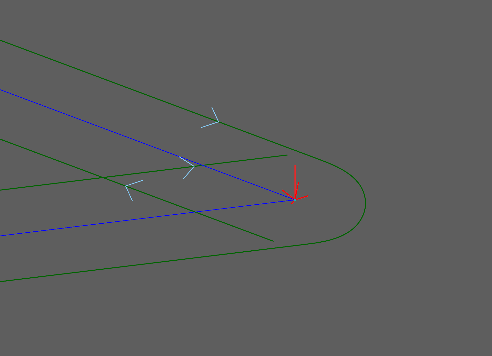 |
| Edge is to short causing adjacent curves to overlap | This error typically occurs at intersections and corners and can be resolved by reconfiguring the network in these areas, which may involve moving or deleting points within the intersection.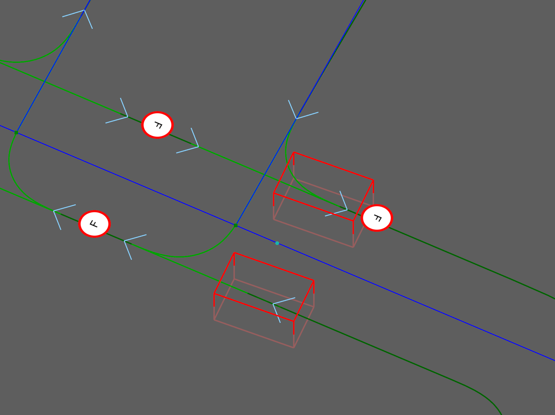 |